
This is a continuation of the axonometric tutorial, be sure to check it out if you get confused!
Perspective Projection
So, up till now we’ve done only parallel projection. This is called like that because all the projection lines we drew were parallel ones.
However, in real life we don’t have parallel projection. This is due to the lens in our eyes.

Convex lenses, as this lovely image from wikipedia shows us, have the ability to turn parallel lightrays into converging ones.
The point where all the rays come together is called the focal point, and the vanishing point in a 2d drawing is related to it as it’s the expression of the maximum distortion that can be given to two parallel lines as they’re skewed toward the focal point.
As you can see from the image, the focal point is not an end-point of the rays. Rather, it is where the rays cross before diverging again… The only difference is that the resulting image will be inverted. Even in our eyes this inversion happens, but our brains are used to this awkwardness since childhood and turn it around automatically.
Let’s see if we can perspectively project our box now.

That went pretty well. As you can see we sort of merged the two sides into one (resulting into the purple side square) so we had an easier time projecting. The projection is limited to one or two vanishing point type projection, so only the horizontal lines get distorted. We can also distort the vertical lines

… to get three-point projection, but this is a bit much. (And I totally made a mistake in there…)
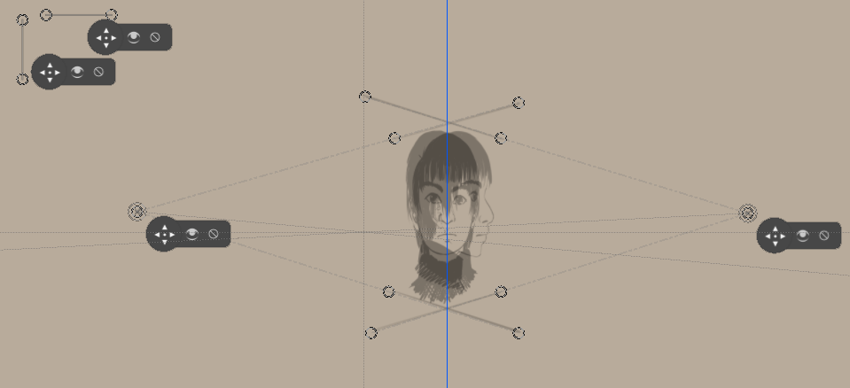
Let’s setup our perspective projection again…
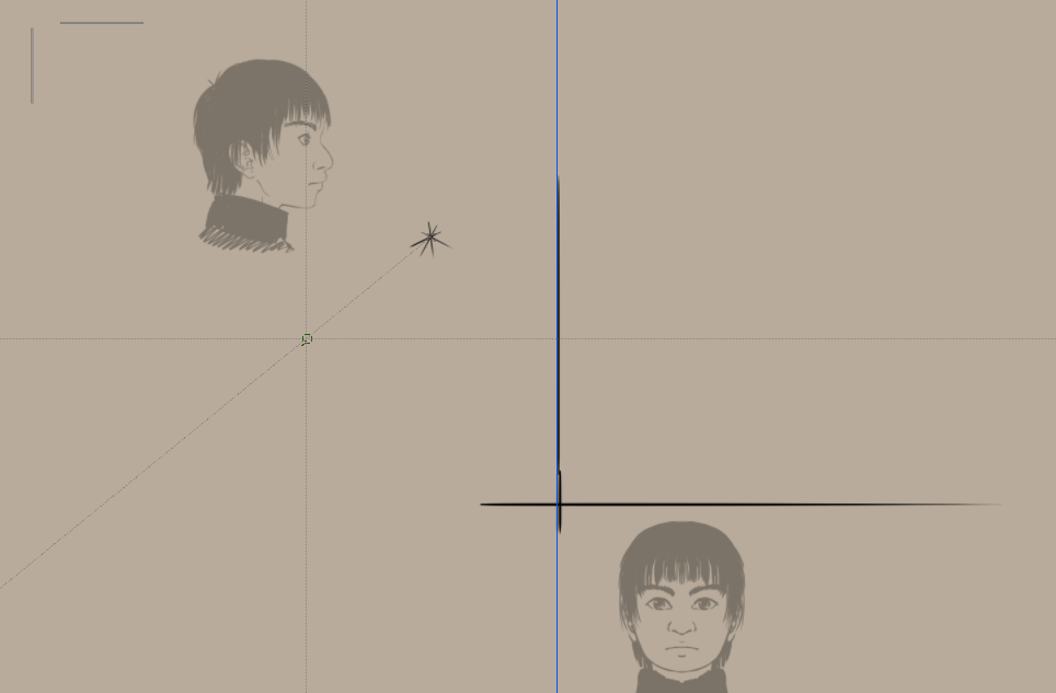
We’ll be using a single vanishing point for our focal point. A guide line will be there for the projection plane, and we’re setting up horizontal and vertical parallel rules to easily draw the straight lines from the view plane to where they intersect.
And now the workflow in GIF format… (don’t forget you can rotate the canvas with the 4 and 6 keys)
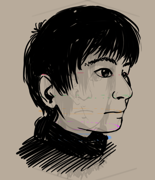
Result:
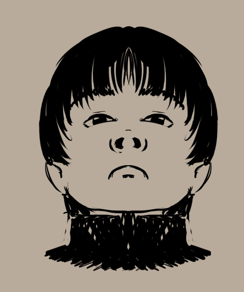
Looks pretty haughty, doesn’t he?
And again, there’s technically a simpler setup here…
Did you know you can use Krita to rotate in 3d? No?
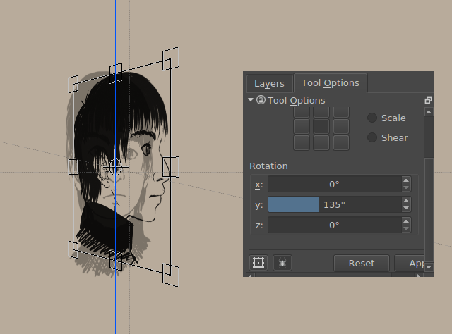
Well, now you do.
The ortho graphics are being set to 45 and 135 degrees respectively.
We draw horizontal lines on the originals, so that we can align vanishing point rulers to them.
And from this, like with the shearing method, we start drawing. (Don’t forget the top-views!)
Which should get you something like this:
But again, the regular method is actually a bit easier…
But now you might be thinking: gee, this is a lot of work… Can’t we make it easier with the computer somehow?
Uhm, yes, that’s more or less why people spent time on developing 3d graphics technology:
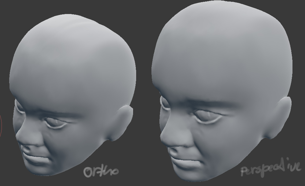
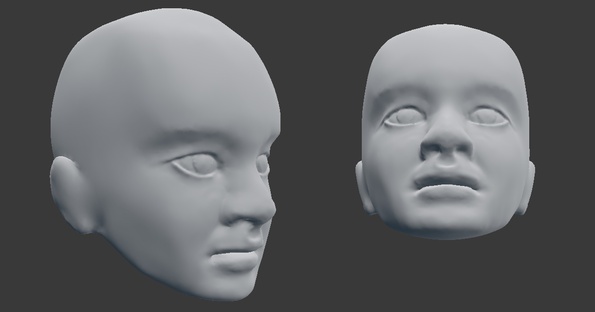
(The image above is sculpted in blender using our orthographic reference)
So let us look at what this technique can be practically used for in the next part…