
This is a continuation of the orthographic and oblique tutorial, be sure to check it out if you get confused!
Axonometric
So, the logic of adding the top is still similar to that of the side.

Not very interesting. But it gets much more interesting when we use a side projection:

Because our cube is red on both front-sides, and blue on both left and right side, we can just use copies, this simplifies the method for cubes a lot. We call this form of axonometric projection ‘dimetric’ as it deforms two parallel lines equally.
Isometric is sorta like dimetric where we have the same angle between all main lines:

True isometric is done with a 90-54.736=35.264° angle from ground plane:

(as you can see, it doesn’t line up perfectly, because Inkscape, while more designed for making these kinds of diagrams than Krita, doesn’t have tools to manipulate the line’s angle in degrees)
This is a bit of an awkward angle, and on top of that, it doesn’t line up with pixels sensibly, so for videogames an angle of 30° from the ground plane is used.

Alright, so, let’s make an isometric out of our boy then.
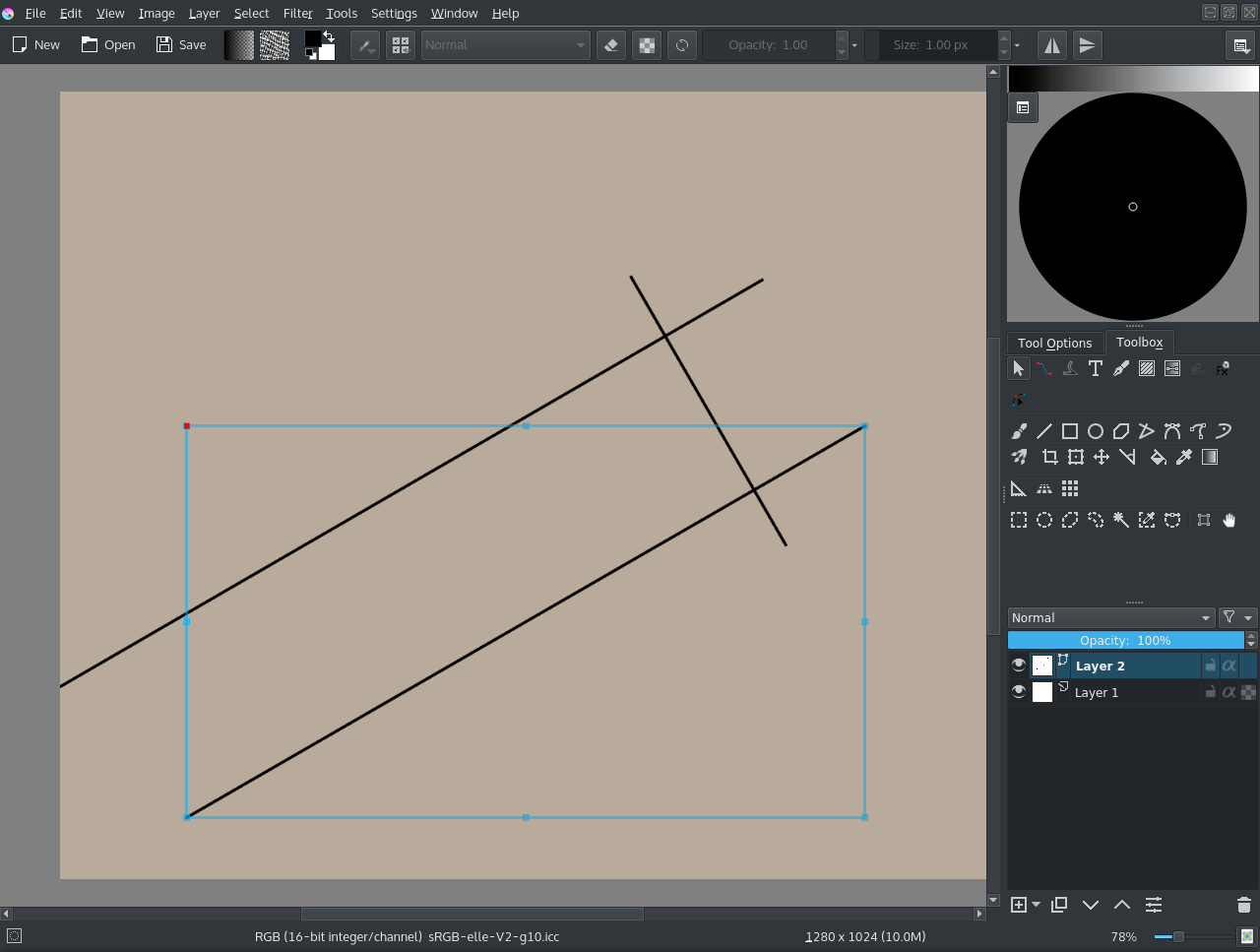
We make a new document, and add a vector layer.
On the vector layer, we select the straight line tool, start a line and then hold the Shift key to make it snap to angles. This’ll allow us to make a 30° setup like above:
We then import some of the frames from the animation via .
Then crop it by setting the crop tool to Layer, and use to remove any background. I also set the layers to 50% opacity. We then align the vectors to them:
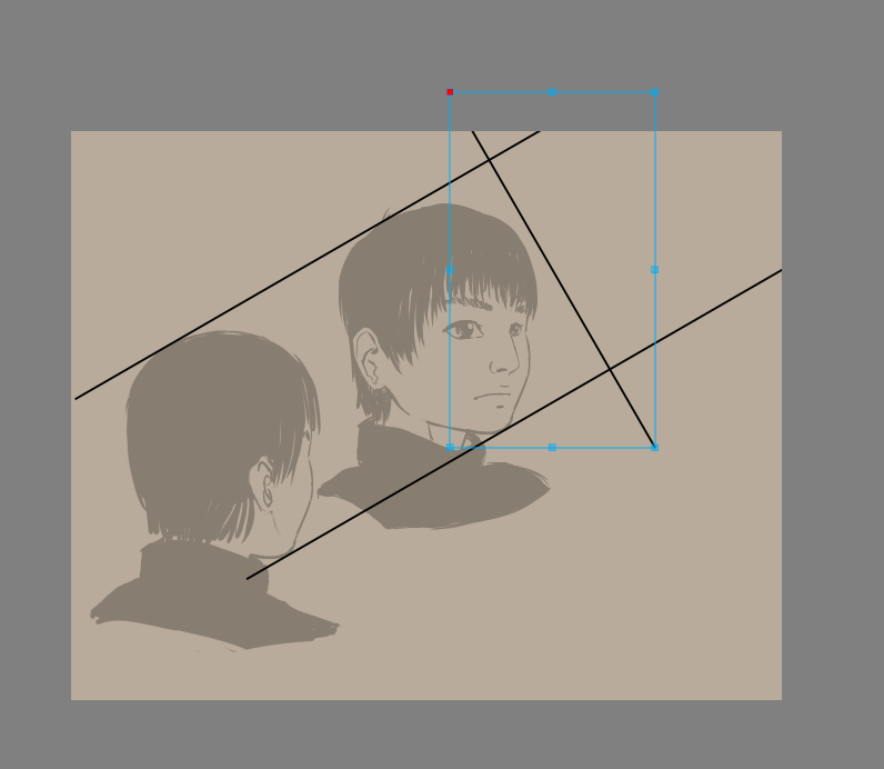
Tip
To resize a vector but keep its angle, you just select it with the shape handling tool (the white arrow) drag on the corners of the bounding box to start moving them, and then press the Shift key to constrain the ratio. This’ll allow you to keep the angle.
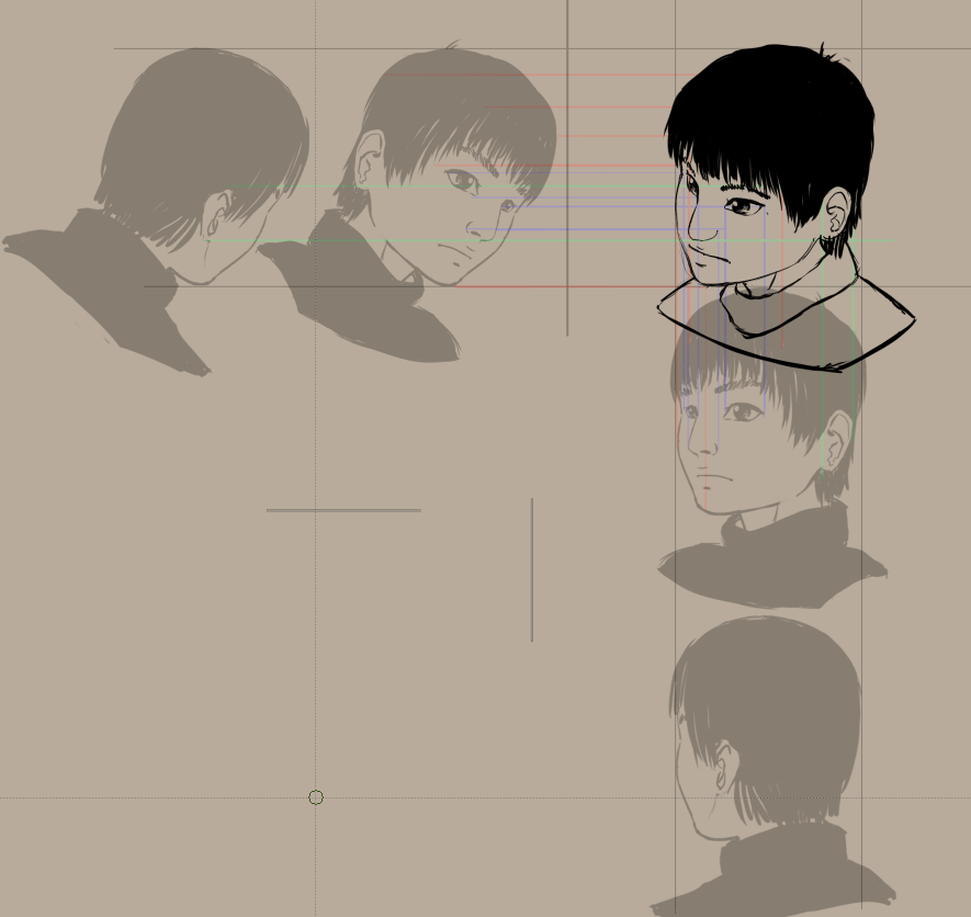
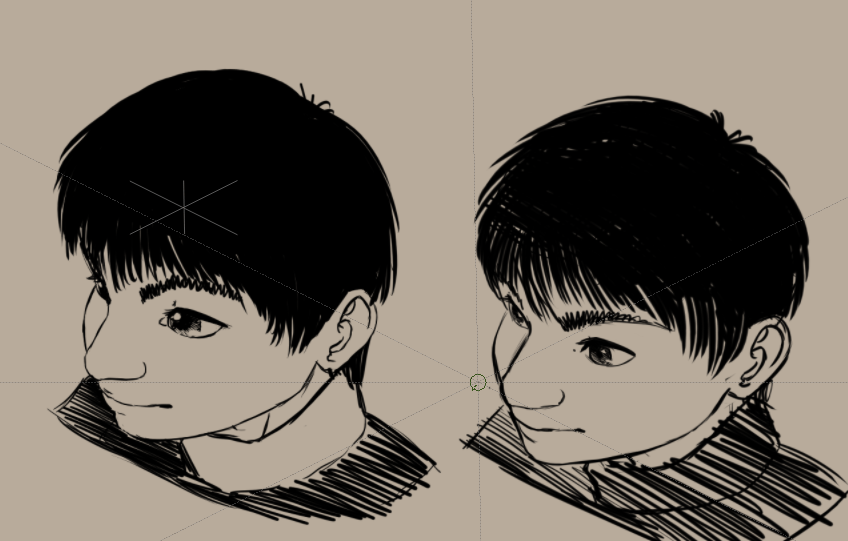
The lower image is ‘the back seen from the front’, we’ll be using this to determine where the ear should go.
Now, we obviously have too little space, so select the crop tool, select Image and tick Grow and do the following:
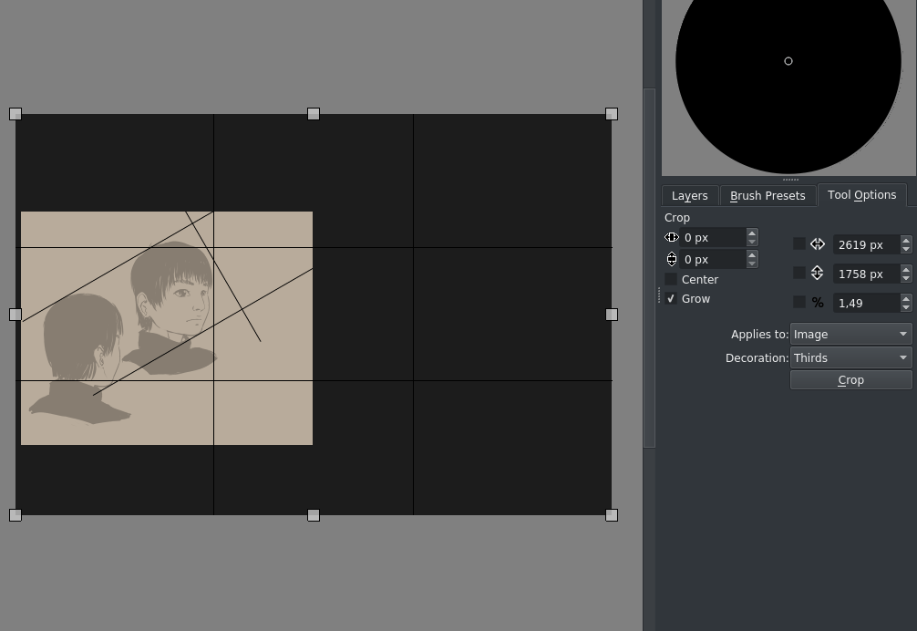
Grow is a more practical way of resizing the canvas in width and height immediately.
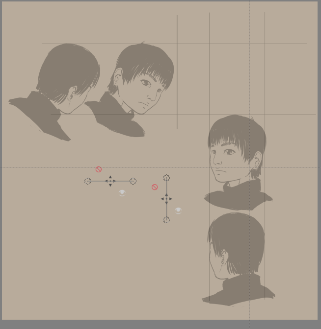
Then we align the other heads and transform them by using the transform tool options:
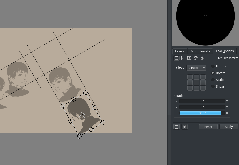
(330° here is 360°-30°)
Our rectangle we’ll be working in slowly becomes visible. Now, this is a bit of a difficult angle to work at, so we go to and fill in 30° clockwise:
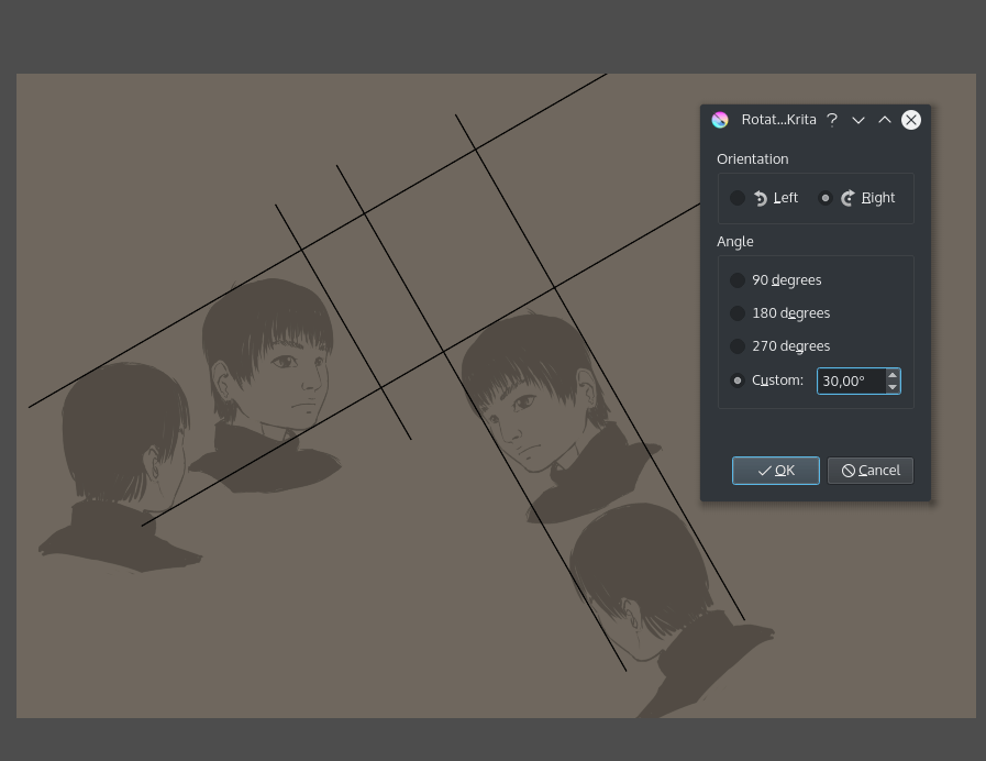
(of course, we could’ve just rotated the left two images 30°, this is mostly to be less confusing compared to the cube)
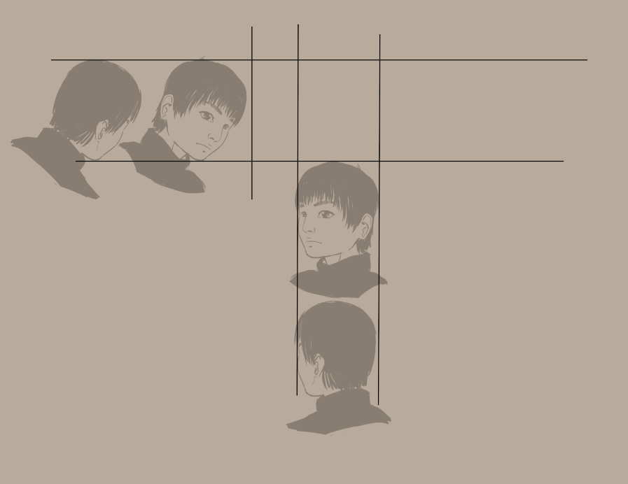
So, we do some cropping, some cleanup and add two parallel assistants like we did with the orthographic:
So the idea here is that you draw parallel lines from both sides to find points in the drawing area. You can use the previews of the assistants for this to keep things clean, but I drew the lines anyway for your convenience.
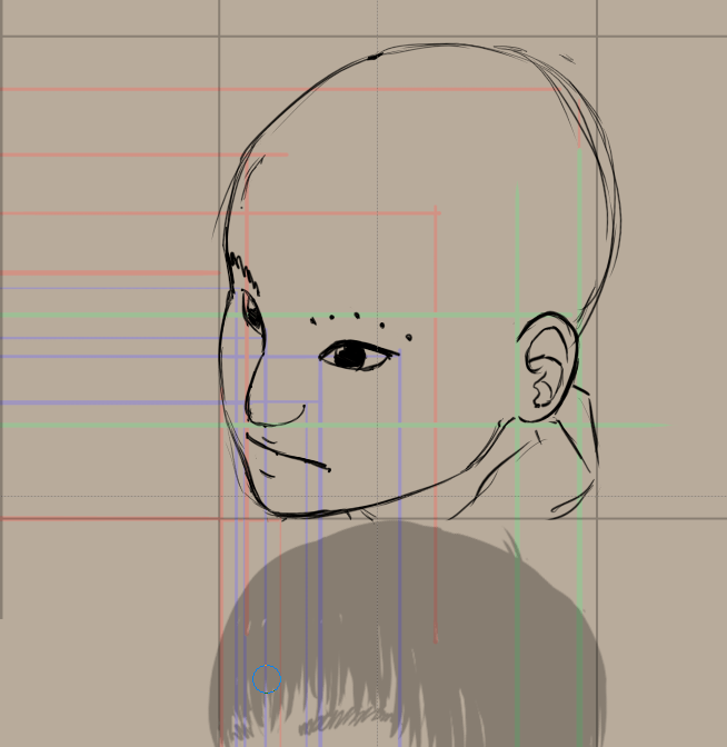
The best is to make a few sampling points, like with the eyebrows here, and then draw the eyebrow over it.
Alternative axonometric with the transform tool
Now, there’s an alternative way of getting there that doesn’t require as much space.
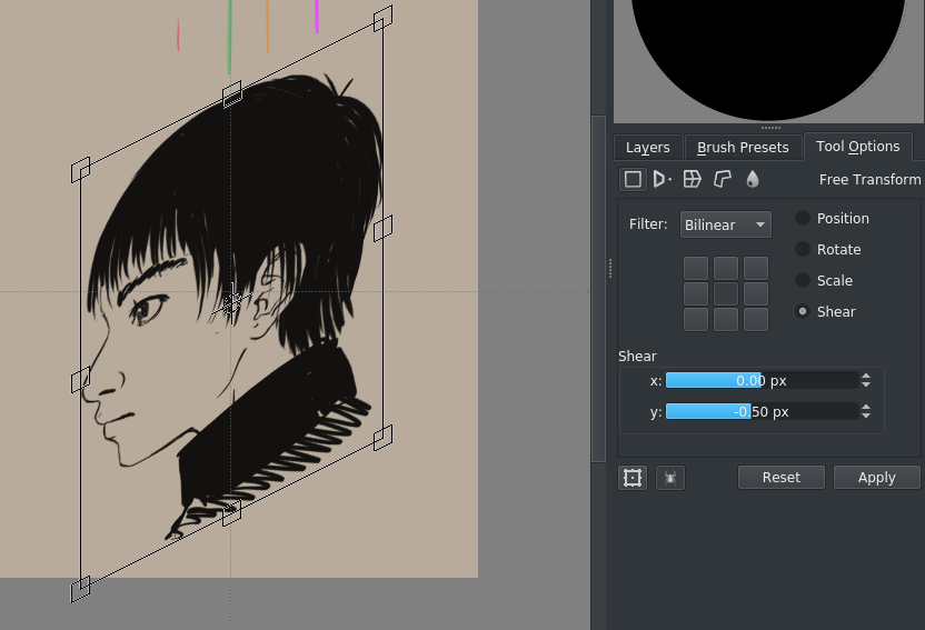
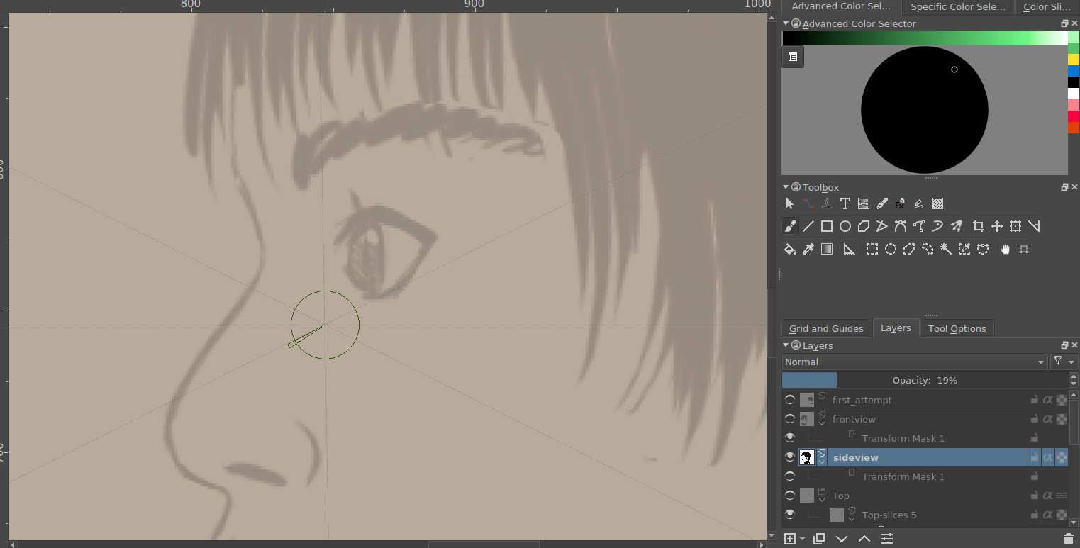
We open our orthographic with Open existing Document as Untitled Document so that we don’t save over it.
Our game-safe isometric has its angle at two pixels horizontal is one pixel vertical. So, we shear the ortho graphics with transform masks to -.5/+.5 pixels (this is proportional)
Use the grid to setup two parallel rulers that represent both diagonals (you can snap them with the Shift + S shortcut):
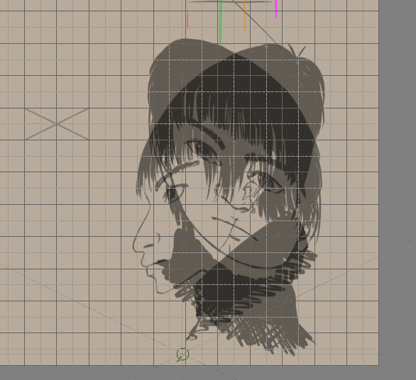
Add the top view as well:
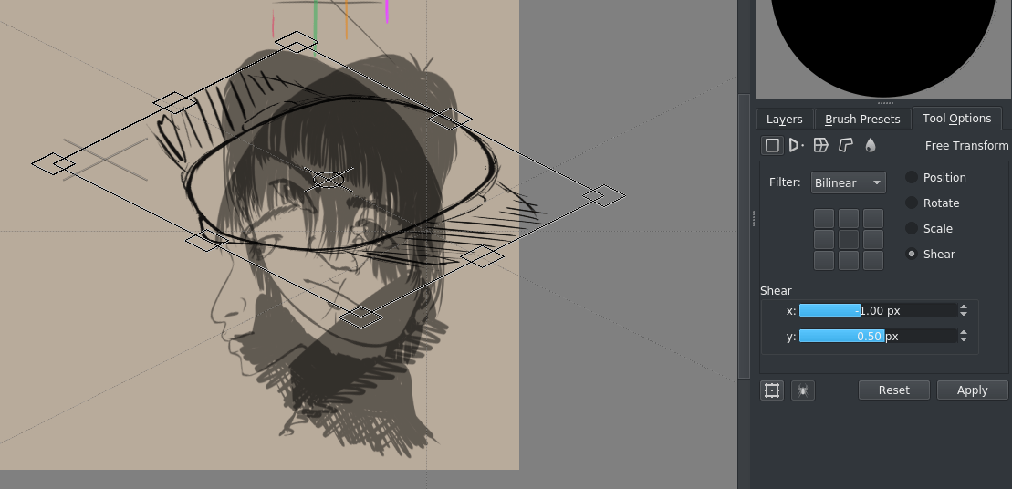
if you do this for all slices, you get something like this:
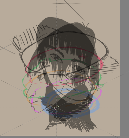
Using the parallel rulers, you can then figure out the position of a point in 3d-ish space:
As you can see, this version both looks more 3d as well as more creepy.
That’s because there are less steps involved as the previous version – We’re deriving our image directly from the orthographic view – so there are less errors involved.
The creepiness is because we’ve had the tiniest bit of stylisation in our side view, so the eyes come out HUGE. This is because when we stylize the side view of an eye, we tend to draw it not perfectly from the side, but rather slightly at an angle. If you look carefully at the turntable, the same problem crops up there as well.
Generally, stylized stuff tends to fall apart in 3d view, and you might need to make some choices on how to make it work.
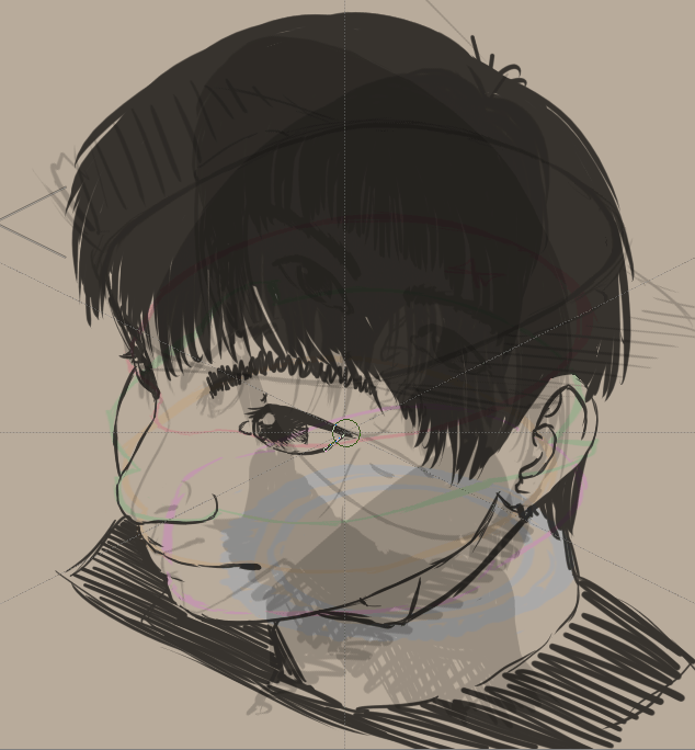
For example, we can just easily fix the side view (because we used transform masks, this is easy.)
And then generate a new drawing from that…
Compare to the old one and you should be able to see that the new result’s eyes are much less creepy:
It still feels very squashed compared to the regular parallel projection above, and it might be an idea to not just skew but also stretch the orthos a bit.
Let’s continue with perspective projection in the next one!